October 31st, 2018
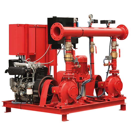
When it comes to fire booster pumps in New York City or any city, all fire pumps rely on two features to simplify matters– a jockey pump and sensing line. The jockey pump keeps the fire pump system pressurized. It is what does the work all of the time. If you have leaks, and you will, the jockey pump fills the system back up. It is very simple to size a jockey pump. It is sized 1% of the fire pump’s flow. If the fire pump runs at 1000 gallons a minute, your jockey pump is 10 gallons a minute. The pressure of the jockey pump should be 110% of the fire pump’s pressure. So if you have a 1000 gallon a minute fire pump at 100 PSI, your jockey pump is sized at 10 gallons a minute at 110 PSI. No exceptions, no reason to go bigger. You do not want bigger. You do not want your jockey pump fighting the fire.
The second key feature of the fire booster pump system is the half inch sensing line going from the high-pressure side of the fire suppression line to the fire pump controller. This sensing line needs to be non-ferrous– brass or copper- and it needs to have two check valves or orifices 3/ 32” large. 3/32” is a very small hole for a reason you don’t want a half inch pressure going into a control panel should the diaphragm to break on the pressure transducer or the burden to break inside a Mercury pressure switch. You only need to sense the pressure in order to trigger the fire pump to start. Those two orifice check valves or orifices of any kind with a 3/32” hole in them need to be five feet apart. The two check valves or orifices are needed to stop any kind of water hammer when the pump shuts off, you don’t want the pressure bouncing and slamming up against the pressure transducer that could cause it to rupture and fail. Make sure, if you use a check valve, the arrows face away from the controller. Also, make sure that the check valves are at least five feet apart and the hole that you drill in the flapper 3/32 inches. Clean it out before you put it in — the small chips can clog the hole. When you tie into the fire pump controller bring your sensing line in so that it Ts up to the controller The bottom of the T should have a valve and a gage, then a valve, then a plug –this is where you test your fire pump.
john@callaghanpump.com,
eileen@callaghanpump.com,
dan@callaghanpump.com,
sales@callaghanpump.com,
service@callaghanpump.com


