March 12th, 2019
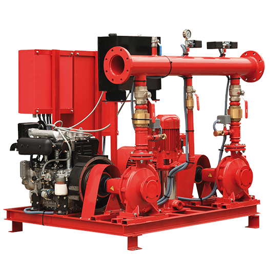
Both fire pump system and jockey pump control panels get their run signal the exact same way through a half inch non-ferrous pipe commonly referred to as a sensing line.
Sensing lines should be piped the exact same way on both the fire and jockey pumps.
The concept is for the fire and jockey pump control system to sense the pressure through the use of 2 orifices(commonly drilled into ½ “check valves) on each sensing line at a distance of a minimum of 5 feet separation which will reduce water hammer which can damage the electronic transducer and the controller. Each orifice should be drilled into the two check valves on each sensing line for a total of 4. The orifices should be 3/32 inch holes drilled into check valves. These valves should be installed in these pipes without damaging the device used to change water pressure into an electronic signal. The arrow on the check valve must face away from the control panel.
The old method was to connect the sensing lines to mercoid switch, but as you can tell by the name this contained mercury, which is no longer allowed. The manufacturer came out with a mechanical non-mercury switch, but while they were inventing this switch, technology surpassed them and transducers are now the approved method of converting water pressure to an electronic signal. The majority of fire pump control panel manufacturers use electronic transducers to sense pressure. Jockey pump control panels are a little more liberal because jockey pumps are not directly required by code. But the code also states that you cannot use the fire pump to maintain system pressure– therefore, unless you plan to use gravity to maintain pressure, you need the jockey pump even though the code does not require it since system pressure needs to be maintained.
Sizing the jockey pump is a simple procedure. It is strictly 1% of the fire pump’s flow and 110% of the fire pump’s pressure.
Transducers use a small rubber diaphragm, a spring, and an extremely small circuit board which converts the position of the spring to an electronic signal. If the spring is compressed, the pressure is high and if it is relaxed the pressure is low. But because transducers do more than turn the pump on and off, we can also scale the amount of spring compression to give us an effective pressure read out. While these transducers represent a change in fire protection, the method of how we send the system’s pressure to them has not changed. The method of piping to the transducer is the same as it was for the old mercoid style.
The first part is understanding that the jockey pump and the fire pump need to be located on the high-pressure side of the fire pump piping. Generally, the layout will be the pump suction or inlet, the pump discharge or outlet, and then you must pipe onto the fire pump discharge piping a ¾ “casing relief valve. This valve needs to be piped into the discharge side of the fire pump, but it must be installed before the fire pump check valve. If you pipe it after the fire pump check valve it will continue to pump water until the discharge pipe equals the same pressure as the valve was adjusted to. The new casing relief valves that Aurora Pumps uses, Cal-Val Model 55L, are absolutely spectacular. L stands for UL which designates a valve used specifically for fire pump use and is insured for the same purpose. Please note that there is an arrow on this valve which indicates the direction of flow. The arrow points to the drain, not to the pipe.
Do not install any isolation valves on this relief valve. If the valve drips, clean it. You can service it by closing the main isolation valves. If it does not seal completely anywhere in its adjustment range, you must repair it (kits are available) or replace it. It is very important that the discharge of this valve be piped down 3-6 inches into a funnel if an air gap is required or below the pump room drain. Make sure the drain cover or screen has a hole in it so this drain from the valve doesn’t spray all over the place. People get upset when their basements flood. I have seen flooded basements more than once, most recently to the tune of $30,000 in damages. The valve is doing its job when it is dumping water and if it is not piped correctly it can cause flooding and possibly significant resulting damage.
john@callaghanpump.com,
eileen@callaghanpump.com,
dan@callaghanpump.com,
sales@callaghanpump.com,
service@callaghanpump.com


